Portfolio

portfolio img

Purdue FSAE — Braking Components

As a subsystem owner for the Purdue Formula SAE team in 2023-24, I designed, analyzed, manufactured, and iterated braking components, a system which encompasses the brake rotors and retainers for the front and rear of the vehicle. Although I largely discuss my own contributions on this page, it was by no means a solo effort, and I am extremely thankful for those who helped me in this process.

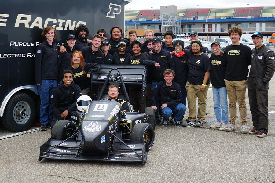
Thanks to the efforts of the dozens of Purdue students on our team, we placed 8th overall at the Michigan SAE competition in May of 2024, as well as claiming 1st in skidpad, 8th in business, and 10th in endurance.
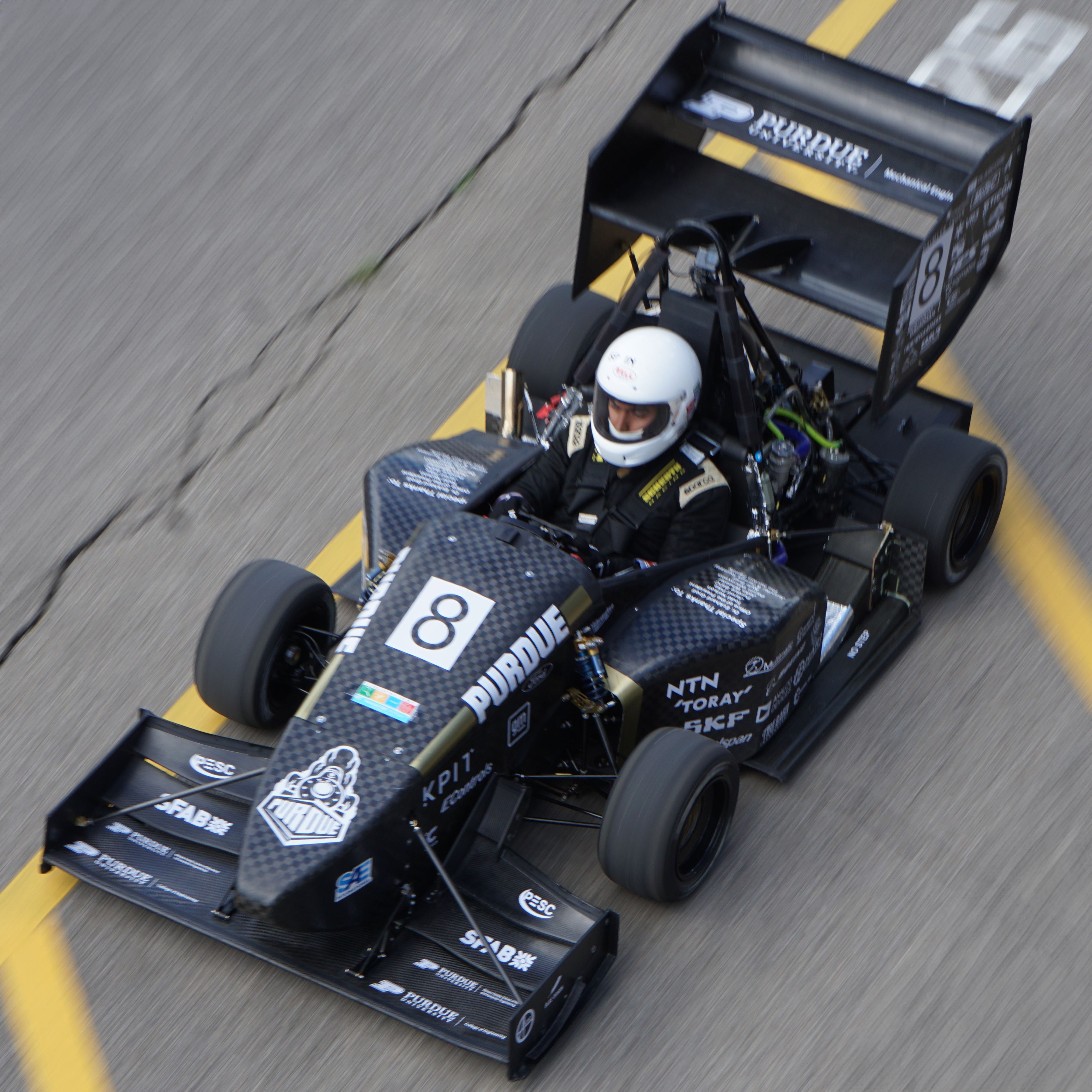
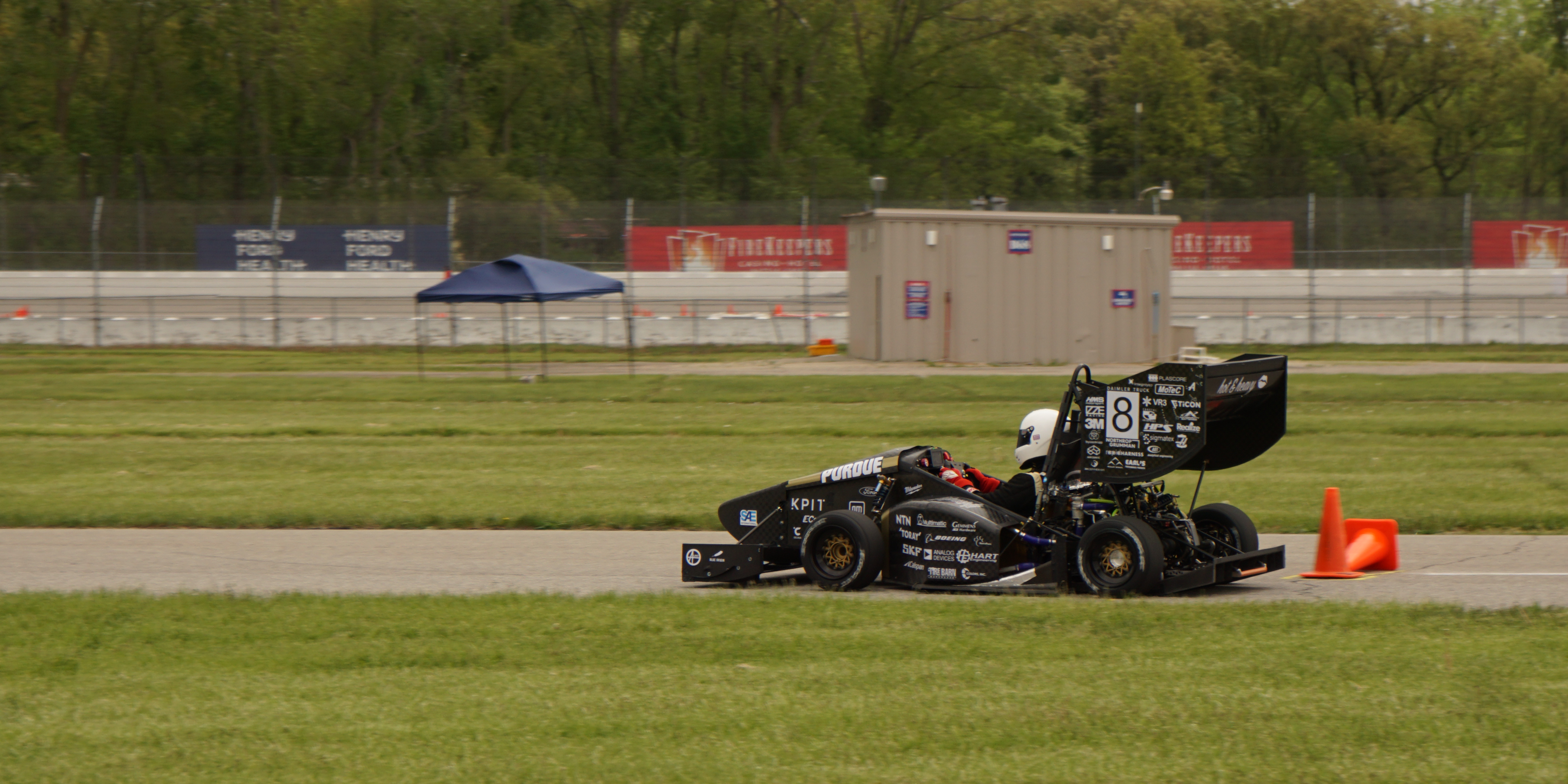
Photo Credits: Zhao Jiang

Design

Over the summer of 2024, I worked with many other students to design a potential brake dynamometer, which would allow the team to test and extrapolate data regarding numerous design factors, such as brake pad and rotor materials, rotor geometry, caliper size, high-temp coatings, and more. Although this didn't pan out due to financial constraints, it led me into the design phase for the braking system on the 2024 competition vehicle.

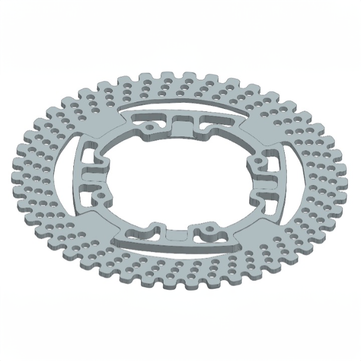
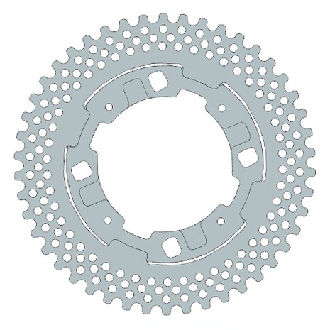
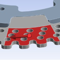
Using Siemens NX (formerly Unigraphics) and Excel calculators, the design phase yielded designs for the front and rear rotors and retainers — four unique parts. This was also the first year it was decided to use aluminum (rather than steel) rear brake retainers for weight savings. Due to the high heat experienced in the front brakes, it was decided too risky to use aluminum front retainers, a factor which ruled out any aluminum rotors for the same reason.

portfolio img
portfolio img
portfolio img

Analysis & Validation

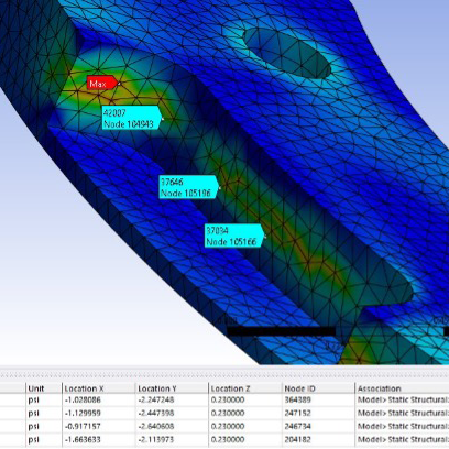
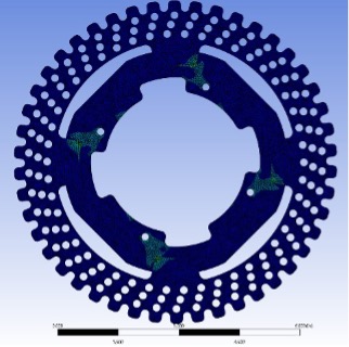
In order to validate the design, the files were exported from NX into ANSYS Finite Element Analysis software. Despite immense troubles with accurate simulation of braking forces, the model eventually yielded an acceptable result that was checked using hand calculations.

portfolio img
portfolio img
portfolio img

Manufacturing

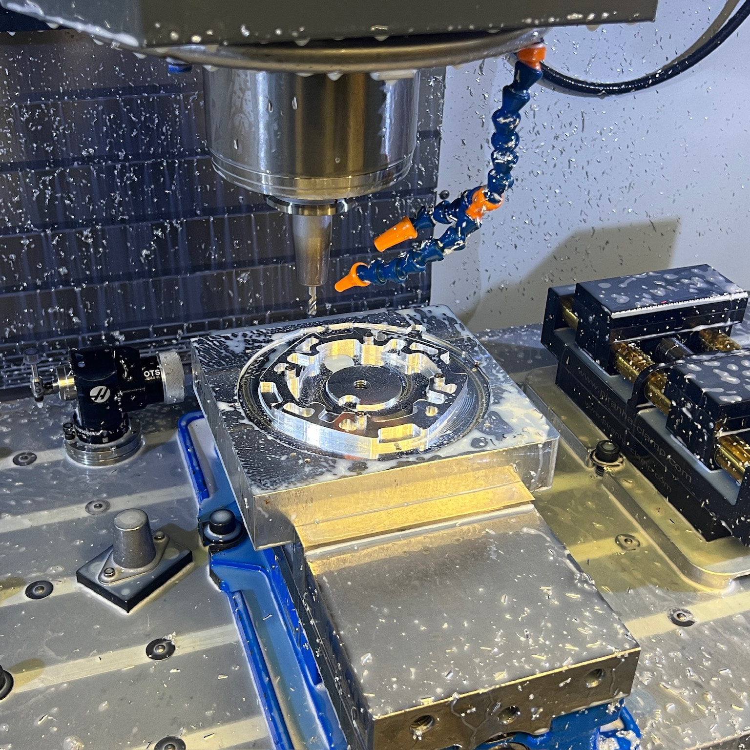
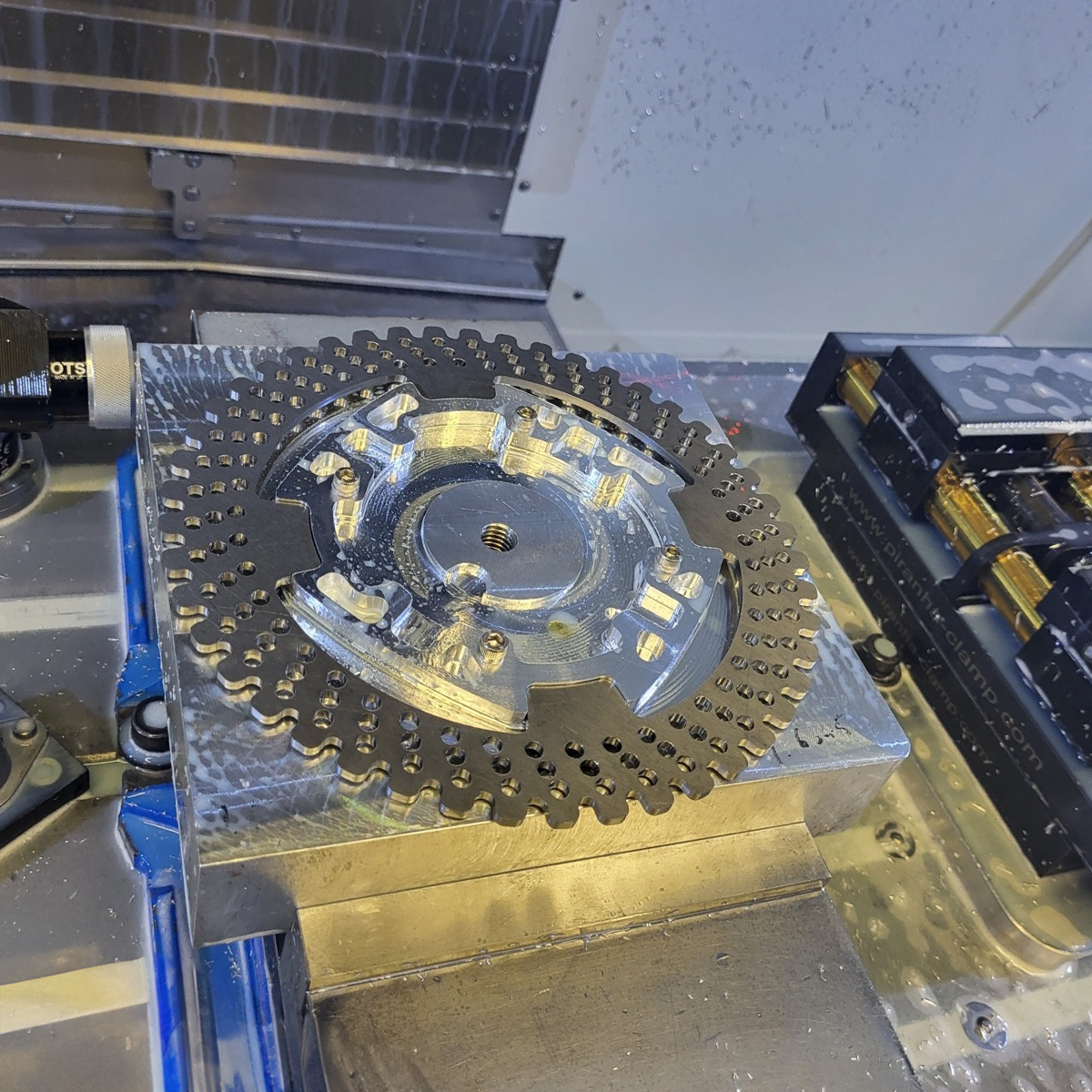
Because manufacturability was a primary concern early in the design cycle, the parts were able to be made relatively simply on a 3-axis CNC mill. I primarily focused on manufacturing of brake retainers, while other members of the team focused on the manufacturing of the brake rotors. With the guidance and assistance of more manufacturing-experienced members of the team, the CAM for all parts was completed within Fusion 360 and was executed on a HAAS VF4 Plate Mill.

Certain aspects of these parts still proved to be difficult to manufacture. All were relatively thin, requiring sacrificial blocks to be faced, drilled, and tapped to prevent drilling into the mill itself. After the parts were clamped to the block, a few holes in the stock would be drilled, after which machine screws would be used to mount the parts to the sacrificial block, thus allowing for the rest of the operations to run. We also encountered issues with the design for 1/8" radii in certain pockets—which although entirely possible, proved risky for tooling—and with the tolerancing between the rotor and retainer connection points.

portfolio img
portfolio img
portfolio img